Überblick
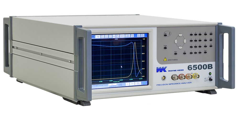
The 6500B series of Precision Impedance Analyzers provide precise and fast testing of components at frequencies up to 120 MHz. Basic measurement accuracy is ±0.05% making the instruments the best in the class.
The accuracy and versatility makes the precision analyzers the ideal choice for many different tasks and applications including passive component design, dielectric material characterisation and manufacturing test.
Engineers need to evaluate component characteristics at high frequencies with high levels of accuracy. The 65120B 120 MHz Precision Impedance Analyzer is therefore ideal for many demanding tasks, combining accuracy and ease of use at an affordable price. If a frequency range up to 120 MHz is not required then other models are available. The 6505B 5MHz instrument is the entry level model in the range.
High measurement accuracy
Capacitance, inductance and impedance basic accuracy is an excellent ±0.05%. Dissipation factor accuracy is ±0.0005 and the quality factor accuracy is ±0.05%.
Graphical sweep of components
The 6500B series of Precision Impedance Analyzers are highly accurate high frequency component analyzers with a host of useful features.
Graphical sweep of two measured parameters is available and displayed on the clear, large, colour display. Swept parameters are frequency, drive level and DC bias.
Display formats available include series or parallel equivalent circuit.
An Equivalent Circuit Anlysis function is available . This allows modelling and curve fitting to various equivalent circuit models. Four types of three component and a four component model are available. The instrument will calculate the nearest equivalent circuit parameters for the measurement traces and revise the results. Alternatively the component parameters may be entered and the instrument will plot the frequency characteristics.
For single frequency measurements a meter mode is available.
Option feature - Polar and Complex Plots & Multi Measurement Mode
Variable drive and bias levels
AC drive levels up to 1V or 20mA can be selected to evaluate components in realistic operating environments.
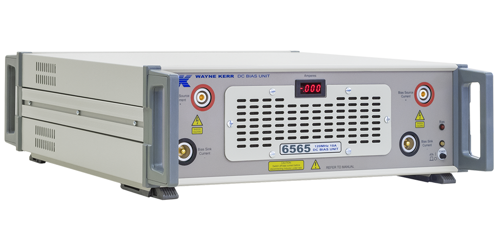
The /D1 DC bias option provides 0 to +40V dc bias voltage and 0 to +100mA dc bias current while the /D2 option provides -40V to +40V dc bias voltage.
External control
The GPIB interface is used to control the instrument and read back measured values for applications such as quality control or for archiving purposes.
An Ethernet interface similarly allows the instrument to be controlled and to send out data - allowing it to be integrated into many test environments.
Wide range of interfaces
An external monitor or projector may be connected to the instrument. The ability to provide a large screen display is invaluable in production environments or for teaching and training.
Instrument control from both a keyboard and mouse is available. Any keyboard or mouse, with either PS/2 or USB interfaces, can be simply connected to provide an alternative method of instrument control and operation.
Data storage and retrieval
All measurement and setup data can be stored using the Ethernet interface or a USB flash memory (supplied as standard).
Setup data
Up to 20 instrument setups may be stored locally for each mode.
Bin handling
The /B1 option (non-isolated 5V) or /B2 option (isolated 24V) signals are available through a 25-way D-type connector. 10 bins can be set using absolute or percentage limits.
Printer outputs
Hard copy printouts can be obtained in a number of ways including direct to an HP-PCL compatible graphics printer or Epson compatible text/ticket printer. A networked HP-PCL compatible printer may also be used via Ethernet connection.
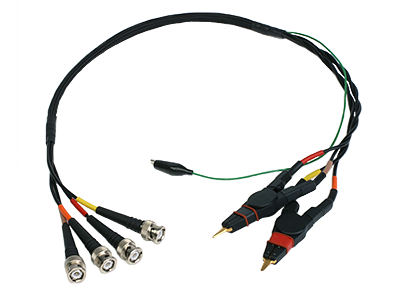
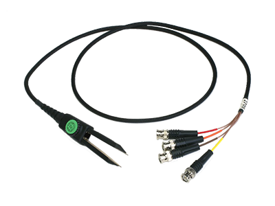
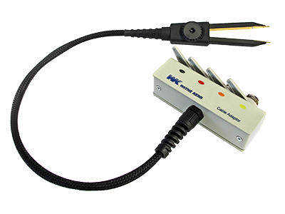
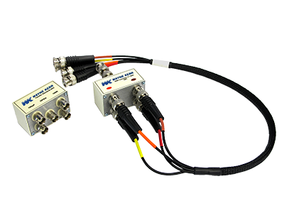
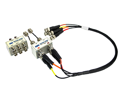
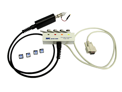
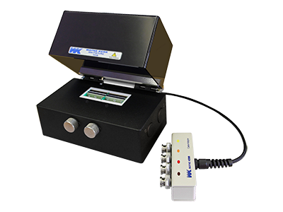
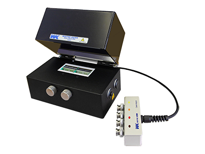
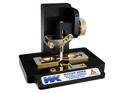
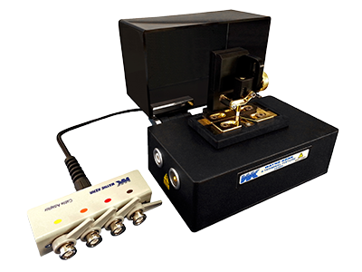
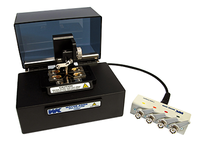
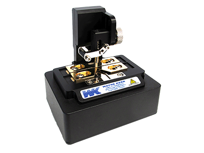
Component connections
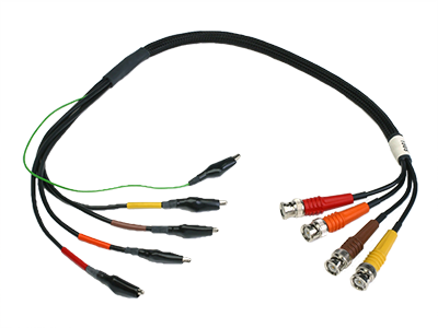
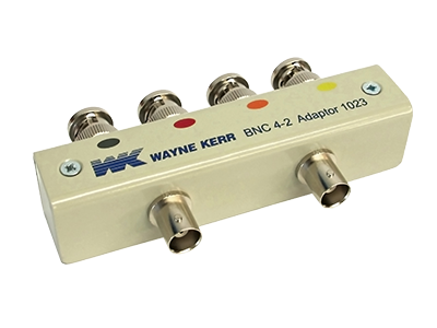
Four front panel BNC connectors permit three or four terminal connections with the screens at ground potential.
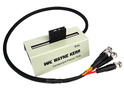
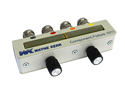
The 1J1011 component fixture, supplied as standard, ensures optimum performance when measuring a wide range of components of leaded components and devices.
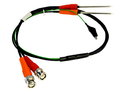
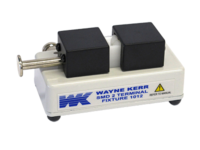
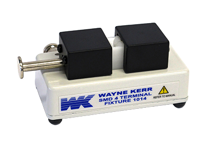
1J1012 (2 Terminal) and 1J1014 (4 Terminal) fixtures allow connection to surface mount devices.
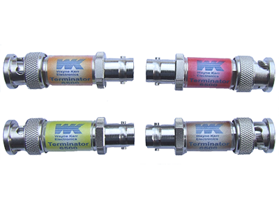
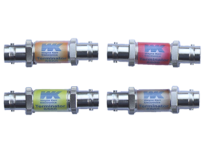
Protection against charged capacitors
High precision measuring instruments can be damaged by charged capacitors which can cause costly repairs and unacceptable downtime. All the models in the range incorporate protection against charged capacitors.
Comprehensive and precise component tests at higher frequencies
The 6500B series capabilities are best summarised by "Comprehensive and precise component tests at higher frequencies". The instruments are the perfect solution for those who have demanding component measurement needs.
Hauptmerkmal
- Grundgenauigkeit 0.05%
- C, L, R, X, G, B, D, Q, Z, Y, Ø – parallel oder seriell
- Charakterisiert Bauteile von 20 Hz bis 120MHz
- Grafische Kurvendarstellung der Messergebnisse
(Frequenzspektrum-Analyse) - vollautomatisierbare Messungen
- Einfache TFT Touchscreen Bedienung
- Resonanzfrequenz-Suchfunktion
- Ersatzschaltbild-Funktion
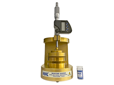
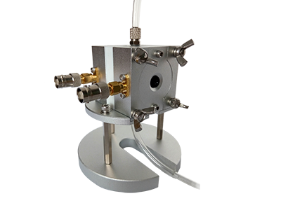
- Material-Test
- Polar- und Komplexdarstellung
- Interfaces / Remote:
GPIB, LAN, VGA, BINNING, Tastatur und Maus
Technische Daten
| Measurement Function | Capacitance (C) Inductance (L) Resistance (R) Reactance (X) Conductance (G) Susceptance (B) Dissipation Factor (D) Quality Factor (Q) Impedance (Z) Admittance (Y) Phase Angle (Ø) |
| Frequency Range | 6505B 20Hz to 5MHz 6510B 20Hz to 10MHz 6515B 20Hz to 15MHz 6520B 20Hz to 20MHz 6530B 20Hz to 30MHz 6550B 20Hz to 50MHz 65120B 20Hz to 120MHz Frequency step size 0.1 mHz Accuracy of set frequency ±0.005"% |
| AC Drive Level | 10 mV or 1V rms (varies with frequency) 200 µA to 20 mA rms (varies with frequency) |
| Measurement Speeds | 4 speeds selectable Up to 20 measurements per second for test frequencies ≧100 Hz |
| Accuracy | Dissipation factor - ±0.0005 (1+D2) Quality factor - ±0.05 %( Q+1/Q) Capacitance / Inductance / Impedance - ±0.05% Accuracy varies with frequency, drive level and measured impedance |
| DC Bias Current (Option) | /D1 0 to +100mA dc bias current and 0 to +40V dc bias voltage /D2 -40V to +40V dc bias voltage |
| Binning (Option) | 10 bins with absolute and percentage limits 25 way d-type interface connector /B1 (Non-isolated) Comon 0V Bin outputs 0 to 5V(normal) with >10mA current sink capability /B2 (isolated) Comon 24V input outputs 0 to 24V with >10mA current source capability |
| Input Specification | Power supply - Input voltage 90 V AC to 264 V AC (Autoranging) Mains frequency 47 to 63 Hz |
| Display | 8.4" VGA (640 x 480) color TFT with touch panel |
| Measurement Connections | Four front panel BNC connectors permit two, three or four terminal connections with the screens at ground potential. 1J1011 Component Fixture (supplied as standard) allows connection to leaded components and devices. |
| Printer | HP-PCL compatible graphics printing (local and network) Centronics / parallel printer port, Epson compatible text/ticket printing (local) |
| Remote Trigger | Rear panel BNC with internal pull-up, operates on logic low or contact closure |
| GPIB Interface | External instrument control 24 pin IEEE 488 connector |
| USB Interface | Two Unversal Serial Bus (USB) interfaces USB 1.1 compliant |
| VGA Interface | 15-way D-type connector to drive an external monitor in addition to the internal screen |
| Network Interface | 10/100-BASETX Ethernet controller RJ45 connector |
| Keyboard Interface | Standard USB or PS/2 keyboard port. Instrument front panel remains active with keyboard plugged in |
| Mouse Interface | Standard USB or PS/2 mouse port Touch screen remains enabled when the mouse is connected |